MPS380 user manual
Introduction
This user manual is an essential part of the dynoKRAFT MPS380 dynamometer.
All functions and settings described apply to the original YourDyno software accordingly.
This product and all it's components are an custom built device designed for professional use, and to be used solely at research and development facilities for such purposes.
© 2022 dynoKRAFT GmbH, all rights reserved.
This manual is copyrighted by dynoKRAFT GmbH, hereinafter referred to as dynoKRAFT. All rights reserved.
Original user manual for the dynoKRAFT dynamometer.
This manual, the controller and / or the software described in it is furnished under license and may only be used in accordance with the terms of this license.
This manual is for informational purposes only, is subject to change without notice and should not be construed as a commitment by dynoKRAFT.
dynoKRAFT assumes no responsibility or liability for errors or inaccuracies that may appear in this manual.
No part of this manual may be reproduced, stored in a retrieval system, or transmitted in any form or by anybody means, electronic, mechanical, recording or otherwise, without the prior written consent of dynoKRAFT.
All trademarks, trade names, service marks, or service names owned or registered by another company and used in this manual are the property of their respective companies.
Manufacturer / Service / Warranty:
dynoKRAFT GmbH
Hugo-Eckener-Str. 33
D-50829 Köln
Germany
Warranty and Disclaimer
This products is meant to be used by trained technicians and tuners only.
Owner/user assumes responsibility for his or her own actions when using these products. dynoKRAFT GmbH hereby expressly disclaims liability and shall not be responsible for incidental, consequential and contingent damages or any kind or nature, including, without limitation: damages to persons or property, whether a claim for such damages is based upon warranty, contract, tort or otherwise; damages due to or arising out of the loss of time; or loss of profits.
dynoKRAFT GmbH shall not be responsible for any damages caused by the presence of error or omission in any of its manuals, instructions or related materials.
Warnings
Conventions used in this manual
The conventions used in this manual are designed to protect both user and equipment and to assure a safe work environment.

Warning!
The warning indicates a serious hazard or risk of machine damage.

Caution.
Caution means that failure to perform or incorrectly perform the described procedure can damage the test bench.

Information.
Information gives the user additional useful advice.
Precautions and dynamometer safety
Your dynoKRAFT engine dyno is a safe and proven way to test the engines performance in a repeatable test conditions.
To assure problem free operations you should note these precautions and use common sense at all times!
To assure problem free operations you should note these precautions and use common sense at all times!
Engines exhaust gasses
Always assure proper dyno room ventilation and use engine exhaust extraction system which is adequately scaled to remove all exhaust gasses from the room in which people are working in.
Fail to do so may result in serious hazard to dyno room operators and will impact engine’s performance.
Warning! Carbon monoxide / Toxic gasses !
Combustion engine exhaust gasses contain toxic carbon monoxide. Breathing it can cause death.
Always operate the dynamometer in well ventilated area. Always use exhaust gasses extraction system during test runs.
Always operate the dynamometer in well ventilated area. Always use exhaust gasses extraction system during test runs.
Noise and debris
Keep in mind that running an engine test at high RPM and Load will create a noisy work environment which may affect one’s ability concentrate on task he’s performing. Prolonged exposure to noise may result in head ache or nausea.
Always use eye protection to avoid eye damage from any debris or dirt which may be found in the air either because of extensive room ventilation or due to equipment damage.
Warning! Excessive noise / Eye damage.
Always use eye and ear protection while working with dynamometer. Fail to do so may result in serious health issues, hearing loss or visual impairment.
Rotating parts
All rotating parts are potential source of serious accident. Therefore always operate the dynamometer with all coverings properly installed. Use additional covering or safety means to secure any visible parts of the engine or dynamometer. Always ware tight sleeves to avoid getting dragged by any rotating parts.
Warning! Rotating parts.
Never operate an dynamometer without properly installed coverings. Always use cloths with tight sleeves.
Fail to do so may result in getting dragged by rotating parts or components.
Heat
During an dynamometer test and substantial amount of heat will be generated by both the engine and dynamometer equipment. The air temperature in the dyno room will rise gradually.
Additionally some surfaces of the combustion or electric engine may get very hot.
dynoKRAFT is encouraging dynamometer operators to use an infrared thermometer to check if the surface temperatures are in safe range. Temperature above 55°C is considered harmful.
Warning! Hot surfaces.
Avoid touching of hot surfaces during and after the dynamometer tests.
Some areas of combustion engines such as exhaust system can get extremely hot and touching them may cause severe tissue burn.
Some areas of combustion engines such as exhaust system can get extremely hot and touching them may cause severe tissue burn.
Electric power. Compressed air
The dynoKRAFT dynamometers are operated using electric power and compressed air (depending on model).
Do not remove any covering panes, perform any service or repairs or open any electric cabinets under power.
Any repairs or service which requires accessing the dynamometers electrical system must be performed by qualified electrician.
Warning! Potentially lethal voltages.
Never perform any service or remove any protective panels or open electric cabinets without previously disconnecting the main AC power cord.
Always wait min. 5 minutes after turning off the dynamometer main switch to allow for complete discharge of electromagnetic coils of the Eddy Current Brakes.
Fail to do so may result in lethal electric shock.
Before performing any service operation or repairs to pneumatic components always release the pressure from the pneumatic system.
Warning! Eye damage.
Always use eye protection while working with dynamometers pneumatic systems.
Fail to do so may result in serious eye damage and visual impairment.
Fail to do so may result in serious eye damage and visual impairment.
General precautions
Always keep minimum safe distance while working with dynamometers so that in case of equipment or engine failure, fire or other hazard the risk of accident is minimized.
Excessive noise or vibration of dynamometer usually indicates serious fault and should be directly solved.
Always verify emergency brake operation before using your dynamometer.
Before performing any tests always verify if the dynamometer and vehicle you’re about to test are properly secured.
Ensure that both the dynamometer and vehicle you’re testing are sufficiently cooled.
Never perform any servicing of the dynamometer unless explicitly recommended in manual..
Caution. Risk of equipment damage. Potential safety hazard.
Not obeying to these rules may result in equipment damage, potential safety hazard to dynamometer operators and can result in loss of warranty.
Specifications and requirements
Permissible operating limits and requirements
| Characteristic |
Value |
Comments |
| Max. RPM |
5000 1/min |
|
| Rotational inertia (without coupling system) |
5,17 kgm²
|
|
| Recommended eddy current brake load for constant operation |
up to 15 Min: 100%
up to 30 Min: 85%
up to 45 Min: 80%
up to 60 Min: 70%
over 60 Min: 60%
|
|
| Eddy current brake coils temperature |
Max. 180 ° C |
The thermostat switches off the power supply to the eddy current brake at ~ 167 ° C.
At ~ 127 ° C the power supply is switched back on again. |
| Power supply |
Value |
Comments |
| Electric power supply |
400V AC / 32A / 50Hz |
see nameplate |
| Environmental and workshop requirements |
Value |
Comments |
| Room temperature |
+10°C to +50°C |
|
| Relative humidity |
10 - 65% |
no condensation |
| PC-System |
preferred: Windows 10 64-Bit |
|
| Internet- and Phone |
Required for software and firmware updates and technical support. |
Dynamometer installation and commissioning
Installation and commissioning
The test stand must be installed on a solid concrete floor with sufficient load-bearing capacity (min. 2 T / m²).
The floor should have a flatness of 2 mm per 1 m (or better).
The MPS380 dynamometer ist not to be operated without adequate fixation of dynamometer chassis which assures correct transfer of counter-torque generated by retarder.
See "Permissible installation scenarios".
Installation and commissioning can only be carried out by a dynoKRAFT technician.
EMC noise
To avoid excessive noise during data transfer, please keep the USB connection / cable between ADAQbase and the computer as short as possible.
Lifting
To lift the dynamometer please use the four (4) hooks provided at each corner of the chassis.
Please make sure to use lifting equipment with adequate load capacity (see machine label)
Permissible installation scenarios
Installation on T-slot table
This is the preferred installation which allows correct counter-torque transfer between engine stand and the dynamometer chassis.
The counter-torque is transferred via the t-slot table, which should be installed on vibration dampers.
Installation on concrete floor / foundation
Warning! Risk of equipment damage.
The supplied rubber machine feet are NOT DESIGNED to transfer counter-torque (reaction forces) from dynamometer chassis directly into foundation!
DO NOT use the dynamometer without assuring correct counter-torque transfer between test engine and dynamometer chassis!
This is the non preferred installation as all the vibrations from dynamometer and tested engine may be transferred directly into floor / foundation.
Further more it is absolutely necessary to assure correct counter-torque transfer between dynamometer chassis and engine stand, for example the engine stand must be firmly bolted to the dynamometer chassis.
To support such installation scenario the dynamometer chassis must be equipped with counter-torque arms.
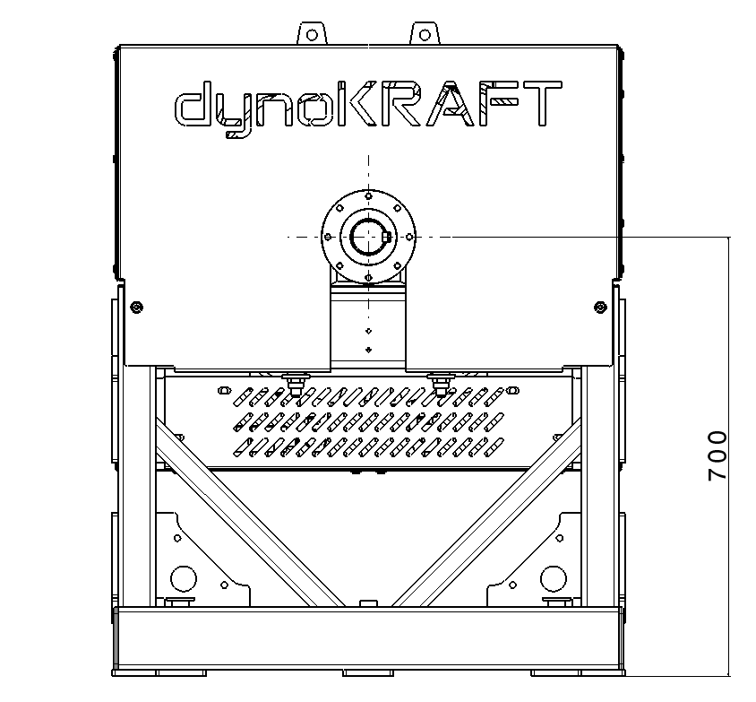
Connecting test engine to the dynamometer
The MPS380 dynamometer is equipped with 180mm flange attachment per DIN 15451 - Part 2.
Please use suitable shaft (cardan-shaft or CV-shaft) to connect the engine to dynamometer flange.
In some cases it is necessary to use elastic torsion clutch to dampen the engine vibrations.
The dynoKRAFT MPS380 is an bi-directional dynamometer.
You can connect your test engine to any of the two input-flanges - please bare in mind the load cell calibration direction.
Axis center height (above t-slot table level) is 700mm.
Caution.
It is in the sole responsibility of the dynamometer operator to cover all rotating parts or use other adequate means to prevent accidents.
Caution.
It is in the sole responsibility of the dynamometer operator to cover all rotating parts or use other adequate means to prevent accidents.
Setting up your workspace
Please setup your workspace so that at least one emergency stop button is within your range at all times while working with your dynamometer / while sitting in the vehicle.
Connecting to Electric Power Supply and Compressed Air Supply
Please connect a power cable to dynamometer main power inlet “MAINS” using adequate extension cable.
Please make sure to use proper electric power source matched to the electric system of the dynamometer.
If in doubt please check the machine label for information on power system used and consult licensed electrician.
The test bench must be connected to a suitable type B residual current circuit breaker, followed by a three-pole 32A fuse, to the mains.
Warning! Obligatory u se of residual current circuit breaker.
A residual current circuit breaker is an obligatory part of the electrical connection of the dynamometer. Failure to comply with this rule can result in severe electric shock or death, e.g. if the insulation is damaged! If the test stand is operated without a residual current circuit breaker, the guarantee expires!
Should your dynamometer be equipped with Air Inlet please connect a suitable compressed air hose to the compressed air inlet adapter. The inlet is a standard 7.4mm workshop quick connector normally found in auto repair shops.
To switch on the dynamometer, please turn the main switch on the side of the switch cabinet to the ON position.
Dyno room
Noise control. Dynamometer room requirements
dynoKRAFT is recommending to setup your dynamometer in noise control room. It is not uncommon, that during combustion engine testing under full load and high RPM the generated noise level is in excess of 120dB
Another important requirement is flammability resistance of your dynamometer room and any equipment you will install inside the room.
The room must also consist of emergency exit wired to the e-stop circuit of your dynamometer. Please consult your local health and safety requirements.
Ensure minimum work space around the dynamometer-test engine setup. dynoKRAFT is recommending a minimum of 2 meters around the dynamometer and engine to allow easy access to all controls and equipment..
Fire hazard
Please ensure that there are a sufficient number of suitable fire extinguishers in the dyno room.
If in doubt, speak to your local health and safety requirements authorities or fire department.
Basic dynamometer operation
Controls
The dynoKRAFT dynamometer is equipped with various external indicators and controls.
Please refer to table below for their meaning and operation.
| Control |
Function |
Comments |
| Emergency stop button (yellow-red) |
Emergency STOP or emergency OFF button. |
By pressing this button the dynamometer will be switched off (retarder power will be cut off). In addition, the pneumatic brakes (if your test bench is equipped with such) are turned on and the rotating rollers are braked.
The emergency stop button is released by pulling it out. |
| "Reset" button (green) |
With the reset button, the dynamometer is reset to normal working conditions after the emergency stop procedure. |
Once all e-stop buttons are released pressing the “reset” button will enable normal dynamometer operation and release the emergency brake. |
| "E-brake ON" LED (yellow) |
This indicator lamp shows that the emergency stop button has been actuated. |
Load Cell calibration
Please follow the steps described in ADAQ Software manual to calibrate the load cell.
Reference load: ~25kg (see supplied calibration weight for exact value or any other weight you use for calibration process).
Torque arm length: 750mm
To install the calibration tool please use the two supplied pins:
E-Stop procedure and reset
The following steps / functions are carried out while the emergency stop button (emergency OFF button) is pressed:
- the test power supply to retarder is switched off
To reset the dynamometer after emergency stop event into normal operation mode please follow these steps:
- Examine the engine and dynamometer and fix any issues with the setup
- Investigate the room for potential hazard
- If you’re not able to identify any potential hazard please release all e-stop buttons and press the “RESET” button
Caution.
Always investigate if the dynamometer chassis and engine stand are firmly fixed and that all bolts are properly tighten after executing E-stop procedure from RPM in excess of 3000.
ADAQbase installation. Basic software configuration
Please refer to the relevant operating instructions:
ADAQbase user manual
ADAQ Software user manual
Check routine before performing a test run
Before performing a test run or starting-up the engine please follow these steps to assure safe dynamometer operation:
- Check if the engine is properly secured on the t-slot table.
- Check if there are no visible leaks or fluid losses in the dynamometer or the engine
- Check the overall technical condition of the engine to be tested (oil level, coolant temperature etc)
- Check if there are not loose parts or tools left on the dynamometer or the engine
- Ensure that any personnel is standing clear of dynamometer or the engine
- Ensure that the dynamometer and engine cooling as well as the exhaust gasses extraction system are operating correctly
Once you have performed these basic checks you should be clear to start up the engine.
These check routine should be performed before every test!
Before you will apply any load to the engine please warm it up. The engine oil temperature should be at least 70°C.
Warning! Lethal hazard.
Leaving any loose parts or tools on the dynamometer or vehicle may result in serious lethal hazard.
Special considerations for Quick-Shifter systems
Many modern vehicles / gearboxes are equipped with dual-clutch transmissions or so called quick-shifter system which allows changing gears under load without using clutch.
Usually these systems operate by cutting ignition which results in reducing load in transmission thus enabling gear change.
Since the dynamometer controller calculates the engine RPM by measuring the retarder RPM and multiplying it by total ratio, changing the gear during a test run will result in incorrect calculated RPM value and may lead to unpredictable conditions.
This is especially true while performing “Manual” or “Power Sweep" tests where the eddy current brake is used to control the calculated engine RPM.
Changing gears with quick-shifter removes the load from the system (ignition cut). The ADAQbase dyno control system will react to these load changes instantly by reducing Eddy Current brake output to 0 and - once the ignition system is back on - applying excessive load to stabilize the sudden change in engine RPM.
The fact that during gear change also the ratio has changed will exaggerate the brake reaction even further.
As a result the excessive load from eddy current brake may be so high that the tie-down straps may break!
Warning! Lethal hazard.
DO NOT use quick-shifter or change gears while recording test runs under full load.
During “Manal” or “Power Sweep" test do not perform any gear changes - especially using quick-shifter mechanism.
This will lead to unstable running conditions and may result in total equipment damage as well as severe injury to operator or death.
Maintenance
Periodic maintenance by the dyno operator
All dynoKRAFT test stands have been developed with a minimum of maintenance to enable problem-free operation for years.
However, as with any high-performance equipment an basic, periodic maintenance is required to ensure problem-free operation.
Warning! Lethal hazard.
Before carrying out maintenance or repair work, always switch off the main power supply of the test bench and unplug the power cord.
Please follow the warnings listed in the "Warnings" chapter!
| What to do |
OK condition |
When to do |
| Check the function of the emergency stop system by pressing the emergency stop button. |
OK condition:
- "Pneumatic brake ON" LED is on |
daily |
| Check whether all covering panels are correctly fixed. |
OK condition:
- all bolts are hand-tightened |
daily |
|
Check that the retarder rotate freely and without any unusual noises.
To do this, please press the "Reset" button beforehand. |
OK condition:
- retarder can be turned freely and without unusual noises |
daily |
| Check weather the fixing bolts to t-slot table are tighten. |
OK condition:
- all bolts are tighten at required torque (depending on bolt size and class) |
daily |
|
Check weather the fixing bolts at input flanges are tighten. |
OK condition:
- all bolts are tighten at required torque (depending on bolt size and class)
|
before each test run
|
Yearly maintenance
The annual maintenance may only be carried out by a qualified technician in accordance with the maintenance plan and reported to dynoKRAFT GmbH by E-mail with date, time and technician name. Any unauthorized maintenance of the dynoKRAFT test stand or failure to perform it will result in the immediate loss of the guarantee.
An initial maintenance must be carried out after 500 operating hours after commissioning.
The maintenance interval is 2000 operating hours or once a year.
It is the customer's responsibility to ensure that annual maintenance is carried out as planned.
Related Articles
ADAQbase user manual
Introduction This user manual is an integral part of the dynoKRAFT ADAQbase dynamometer controller hardware. All described functions and settings are applicable for the original YourDyno controller. ©2022 dynoKRAFT GmbH, all rights reserved. This ...ADAQ Software user manual
This user manual is an integral part of the dynoKRAFT ADAQbase dynamometer controller software. All described functions and settings are applicable for the original YourDyno software. ©2022 dynoKRAFT GmbH, all rights reserved. This manual is ...ADAQexiom user manual
Introduction This user manual is an integral part of the dynoKRAFT ADAQexiom expansion module hardware and software plugin. ©2022 dynoKRAFT GmbH, all rights reserved. This manual is copyrighted by dynoKRAFT GmbH, hereafter referred to as dynoKRAFT, ...Xencelabs Quick Keys remote user manual
Introduction This user manual is an integral part of the dynoKRAFT ADAQ Software. The Xencelabs Quick Keys remote is a product of Xencelabs Technologies Ltd. (www.xencelabs.com) ©2022 dynoKRAFT GmbH, all rights reserved. This manual is copyrighted by ...A200- / A330- and A380-Series user manual
Introduction This user manual is an essential part of the dynoKRAFT A200-2WD / A200-4WD-ML / A330-2WD / A330-4WD-ML / A380-2WD and A380-4WD-ML dynamometer. All functions and settings described apply to the original YourDyno software accordingly. This ...