ADAQbase user manual
Introduction
This user manual is an integral part of the dynoKRAFT ADAQbase dynamometer controller hardware.
All described functions and settings are applicable for the original YourDyno controller.
All described functions and settings are applicable for the original YourDyno controller.
©2022 dynoKRAFT GmbH, all rights reserved.
This manual is copyrighted by dynoKRAFT GmbH, hereafter referred to as dynoKRAFT, all rights are reserved.
Original User Manual for dynoKRAFT ADAQbase dynamometer controller hardware.
This manual the controller and/or software described in it, is furnished under license and may only be used in accordance with the terms of such license.
This manual is furnished for informational use only, is subject to change without notice, and should not be construed as a commitment by dynoKRAFT.
dynoKRAFT assumes no responsibility or liability for any error or inaccuracies that may appear in this manual.
No part of this manual may be reproduced, stored in a retrieval system, or transmitted, in any form or by any means, electronic, mechanical, recording, or otherwise, without the prior written permission of dynoKRAFT.
Any trademarks, trade names, service marks, or service names owned or registered by any other company and used in this guide are the property of their respective companies.
Manufacturer / Service / Warranty:
dynoKRAFT GmbH
Hugo-Eckener-Str. 33
D-50829 Köln
Germany
Hardware setup
Connecting ADAQbase hardware to Windows PC

This manual assumes that you have the latest ADAQ software installed on your Windows 7 or 10 PC as described in other section of this wiki (see: ADAQ software main article)
and that the PC has active internet connection and all Windows Updates are installed.
and that the PC has active internet connection and all Windows Updates are installed.
The ADAQ dynamometer controller package (hardware and software) is designed to be used with Windows 7 or Windows 10 both 32- and 64-bit versions. dynoKRAFT provides support only for these two operating systems.
Driver installation - Windows 10
On Windows 10 PC the required USB-Driver will be installed automatically upon plugin-in the USB cable.
Driver installation - Windows 7
On Windows 7 PC you must manually install USB-UART the diver upon connecting the ADAQbase.
Download drivers from here: <see article attachments> and unzip the package to any location.
Manual driver installation:
1. You can either wait for Windows to show a message that it can't find correct drivers online or press "Skip obtaining diver software from Windows Update" - confirm with OK in following window.
2. Open "Device Manager" from Start Menu and navigate to "Other devices"
3. Select "USBUART" with mouse and Right-Click it.
4. Select "Update Driver Software"
5. Select "Browse my computer for driver software"
6. Click the "Browse" button and navigate to folder with unzipped USB-UART driver you downloaded previously. Confirm with OK.
7. Press "Next" and in the following window with "Windows Security" warning confirm that you wan't to install the drive anyway.:
8. After successful installation the "Cypress USB UART (COMxx)" device will appear under "Ports (COM & LPT)" section of Device Manager.:
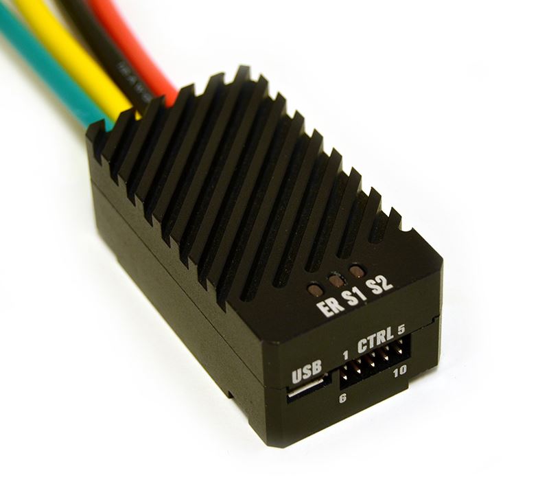
Connecting the USB cable to ADAQbase
To connect ADAQbase to PC simply connect the supplied USB-cable to free USB port on your PC.
Plug the other end of the USB-cable to ADAQbase "USB" port.
Plug the other end of the USB-cable to ADAQbase "USB" port.
From this point onward the ADAQ software will connect to ADAQbase controller automatically whenever you plug-in the USB cable.
Should you experience any connection problems between ADAQ software and ADAQbase controller please see: FAQ | Troubleshooting section below
RPM 1 and RPM 2 inputs
The ADAQbase controller comes equipped with two RPM inputs: RPM 1 and RPM 2.
These inputs can be configured to either read Roller or Engine RPM and support any digital input signal.
Please check corresponding section in ADAQ software manual for details on how to configure the inputs.
Please check corresponding section in ADAQ software manual for details on how to configure the inputs.
Default RPM input configuration
dynoKRAFT A200-series, M120-pro, M200-evo, A380-2WD, MPS-series, MPSW-series:
RPM 1: roller RPM (or retarder RPM) from built-in Hall-Sensor
RPM 2: Default: engine RPM from ignition pick-up | Optional: any other digital RPM signal
dynoKRAFT A380-4WD-ML:
RPM 1: REAR roller RPM (or retarder RPM) from built-in Hall-Sensor
RPM 2: FRONT roller RPM (or retarder RPM) from built-in Hall-Sensor
Input screw terminals definition
SHD - shield (it is advisable to used shielded wires)
0V - negative terminal, sensor power supply
SIG - signal
V+ - positive terminal, sensor power supply (max. 5V DC)

The V+ terminal is not to be used as power source for external equipment!
Setting up the specific RPM 1 or RPM 2 -input as Roller RPM signal will also define the corresponding Out 1 or Out 2 and LC 1 or LC 2 terminals as dynamometer control inputs/outputs.
LC 1 and LC 2 inputs
The ADAQbase controller comes equipped with two Load Cell input screw terminals:
LC 1 = Load Cell 1
LC 2 = Load Cell 2
LC 1 = Load Cell 1
LC 2 = Load Cell 2
Each input can support any analog Load Cell that does not have any sort of built-in amplifier.
Connecting and 4-wire load cell
To connect an 4-wire load cell to ADAQbase simply attach corresponding wires to correct screw terminals.:
SHD - shield (it is strongly advisable to use shielded wire)
SHD - shield (it is strongly advisable to use shielded wire)
0V - negative terminal, excitation -
SIG+ / SIG- - load cell signal + / -
5V - positive terminal, excitation -
5V - positive terminal, excitation -
The 5V terminal is not to be used as power source for external equipment!
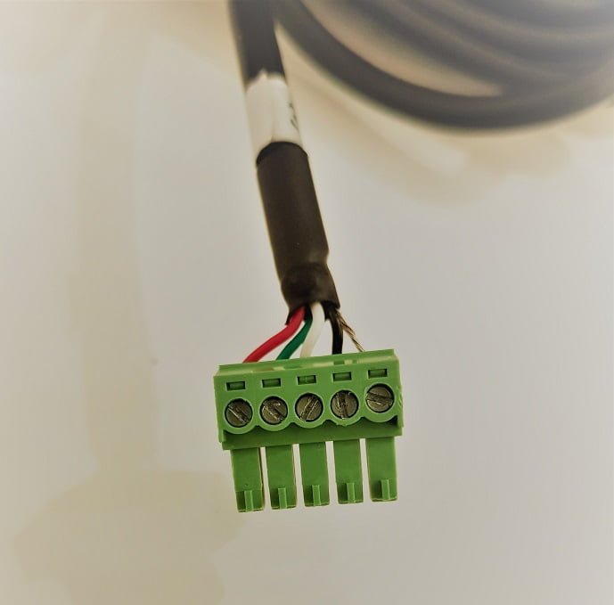
This is how an typical load cell connection looks like:
Connecting and 6-wire load cell
In some cases your dyno may be equipped with 6-wire load cell. This means that there two "signal" wires and two "sense" wires.
These are to be connected as an pair to the respective SIG+ or SIG- terminal:
Connect "Signal+" and "Sense+" wires to SIG+ terminal on ADAQbase
Connect "Signal-" and "Sense"- wires to SIG- terminal on ADAQbase
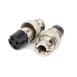
Connecting to Load Cell through DIN 4-way connector
In some cases your dyno might be equipped with an DIN 4-way female connector as shown below.
The pin-out for this connector is as follow:
Pin 1 and 4 - SIG+ and SIG-
Pin 1 and 4 - SIG+ and SIG-
Pin 3 - 5V
Pin 2 - 0V (ground)
ThC, Aux1, Aux2 Aux3 inputs
The ADAQbase controller is equipped with 4 general sensor inputs.:
ThC - thermocouple Type-K input
ThC - thermocouple Type-K input
Aux1 ... Aux3 - general 0-5V analog input with configurable, linear sensor interpolation
Connect the external sensors to corresponding screw terminals
0V - ground
SIG - sensor signal max. 5V DC
Th+ / Th- - thermocouple + / K
Sensor configuration and analog input signal interpolation is described in ADAQ software user manual (see: ADAQ software main article)
It is strongly advisable to measure the sensor voltage that is used for interpolation directly at ADAQbase input terminals.
In some cases you may need to "shift" the interpolation (taken for example from Workshop Manual) by specific value due to voltage drop.
It is not uncommon that when using longer extension cable between the actual sensor and ADAQbase the voltage reading will be lower at input terminals then directly at sensor.
It is not uncommon that when using longer extension cable between the actual sensor and ADAQbase the voltage reading will be lower at input terminals then directly at sensor.

Additional analog inputs can be added using ADAQexiom expansion module.
DIG I/O digital input/output
Provision for future functions.
OUT1 and OUT2 outputs
The ADAQbase controller is equipped with two output signals: OUT1 and OUT2
Each channel is offering two channels A and B
Each channel can be configured as Analog-Output or PWM-Output
Analog Output:
This mode is used to control Eddy Current Brake power supply and it's the default operation mode.
PWM-Output:
This mode can be used to perform following tasks:
- Drive an RC servo, typically for water brakes or hydraulic brakes
- Drive an RC servo, typically for water brakes or hydraulic brakes
- Drive a servo motor using a motor controller
- Drive a Stepper motor controller
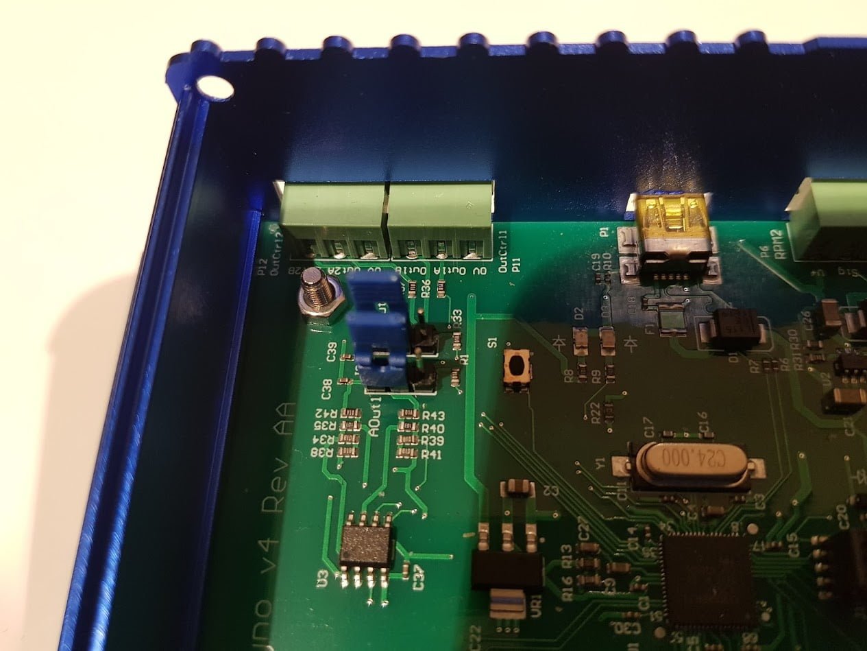
Selecting the output mode
In order to select the analog output, move the two blue jumpers to the position as shown below (marked AOut1 and AOut2).
The other position is used for PWM and stepper motors.
Eddy Current Brake power supply control
To control an Eddy Current Brake power supply (PWS) make sure to set the Output mode to Analog for the respective signal Out1 or Out2 depending on which RPM-input you are using to measure the dynamometer RPM.
Connect the 0V from ADAQbase to "Input 0V" terminal on power supply.
Connect the OutB from ADAQbase to "Input Signal" terminal on power supply.
RC Servo control
For dynos requiring the control of a valve, for example Water Brake dynos, you can use an RC servo or Servo motor or a stepper motor.
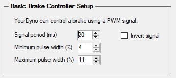
Here is how to connect a servo to ADAQbase:
With these PWM parameters, ADAQbase can directly control the RC servo.
All RC servos will require a external power supply as they cannot be powered directly from ADAQbase controller.
Servomotors
Servo motors are motors that run to a certain position based on the input. So they work much like an RC servo, but they can be very powerful.
They can be linear or rotational. They are controlled using either a built in or separate servo controller.
They can be linear or rotational. They are controlled using either a built in or separate servo controller.
They can all use a PWM as input, so they are controlled directly by ADAQ software.
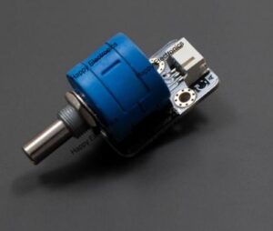
Servo motors come finished with built in encoders or you can use a standard motor and add your own encoder. You should use a potentiometer type encoder (not a quadrature encoder). They are very simple in operation; if fed by 5V they give out a 0V-5V signal based on the absolute rotational position. Make sure to choose one that has at least as many turns as you need to control your valve. Using a potentiometer encoder you achieve absolute position control, which is what you need. A specific output from ADAQ software will translate into an absolute position of your valve.
There are many potentiometer encoders to choose from. Some are hollow shaft and go directly onto your motor shaft. Here is a cheap option with 3600 degree (10 rotations) operating range. It can be connected to for example the Roboclaw controller to turn a DC brushed motor into a servo motor:
FAQ | Troubleshooting
ADAQbase not connecting
In some cases the USB UART driver can get corrupted or stop working.
Root cause:
USB driver is not installed or corrupted
USB driver is not installed or corrupted
Solution:
1. Unplug the USB cable from PC.
2. Make sure that the PC has active internet connection and that no Windows-Update services are deactivated.
1. Unplug the USB cable from PC.
2. Make sure that the PC has active internet connection and that no Windows-Update services are deactivated.
3. Make sure that any third-party Firewall is not blocking the internet for Windows-Update services.
4. Open "Device Manager" from Windows Start Menu and check if USBUART device is highlighted with error:
5. If that's the case re-install the driver (see: Driver installation - Windows 7 section of this manual)
Related Articles
ADAQ Software user manual
This user manual is an integral part of the dynoKRAFT ADAQbase dynamometer controller software. All described functions and settings are applicable for the original YourDyno software. ©2022 dynoKRAFT GmbH, all rights reserved. This manual is ...ADAQexiom user manual
Introduction This user manual is an integral part of the dynoKRAFT ADAQexiom expansion module hardware and software plugin. ©2022 dynoKRAFT GmbH, all rights reserved. This manual is copyrighted by dynoKRAFT GmbH, hereafter referred to as dynoKRAFT, ...MPS380 user manual
Introduction This user manual is an essential part of the dynoKRAFT MPS380 dynamometer. All functions and settings described apply to the original YourDyno software accordingly. This product and all it's components are an custom built device designed ...A200- / A330- and A380-Series user manual
Introduction This user manual is an essential part of the dynoKRAFT A200-2WD / A200-4WD-ML / A330-2WD / A330-4WD-ML / A380-2WD and A380-4WD-ML dynamometer. All functions and settings described apply to the original YourDyno software accordingly. This ...M120-pro M200-evo user manual
Introduction This user manual is an essential part of the dynoKRAFT M120-pro / M200-evo dynamometer. All functions and settings described apply to the original YourDyno software accordingly. This product an all it's components are an custom built ...