ADAQ Software user manual
This user manual is an integral part of the dynoKRAFT ADAQbase dynamometer controller software.
All described functions and settings are applicable for the original YourDyno software.
©2022 dynoKRAFT GmbH, all rights reserved.
This manual is copyrighted by dynoKRAFT GmbH, hereafter referred to as dynoKRAFT, all rights are reserved.
Original User Manual for dynoKRAFT ADAQbase dynamometer controller software.
This manual the controller and/or software described in it, is furnished under license and may only be used in accordance with the terms of such license.
This manual the controller and/or software described in it, is furnished under license and may only be used in accordance with the terms of such license.
This manual is furnished for informational use only, is subject to change without notice, and should not be construed as a commitment by dynoKRAFT.
dynoKRAFT assumes no responsibility or liability for any error or inaccuracies that may appear in this manual.
No part of this manual may be reproduced, stored in a retrieval system, or transmitted, in any form or by any
means, electronic, mechanical, recording, or otherwise, without the prior written permission of dynoKRAFT.
Any trademarks, trade names, service marks, or service names owned or registered by any other company and used in this guide are the property of their respective companies.
Any trademarks, trade names, service marks, or service names owned or registered by any other company and used in this guide are the property of their respective companies.
Manufacturer / Service / Warranty:
dynoKRAFT GmbH
Hugo-Eckener-Str. 33
D-50829 Köln
Germany
Hardware
ADAQbase
At first please install the ADAQ Software, ADAQexiom plugin and ADAQexiom driver before connecting any hardware to your PC.

Please refer to ADAQbase user manual on how to install the ADAQbase hardware and corresponding drivers.
PC requirements
Operating System: Windows 10
CPU: To assure fast and reliable operation of ADAQ software please use CPU with Benchmark score of min. 5000.
Recommended score is 10000 or higher.
See: https://www.cpubenchmark.net/mid_range_cpus.html for CPU list.
Connectivity:
- Min. 3x USB 3.0 directly on Motherboard.
NOTE: it is not allowed to connect ADAQbase or ADAQexiom via USB HUB (also internal to PC case !) - this may significantly impact data connection performance between the controller and software.
- Integrated Bluetooth LE (4.0 or newer) optionally, external BT LE dongle
- LAN or WLAN connection
Software installation

To install the ADAQ software please download the latest installation package from www.dynoKRAFT.de website.
1. After downloading the installation package please execute the file "dynoKRAFTinstaller_x.x.xx.exe".
NOTE: x.x.xx stands for version number.
Press the button "Next" to start the installation wizard.
2. Please select at minimum following plugins from the list. You may add more plugins if you wish to.
Please note that all listed plugins are third-party add-on's for which we provide no support.
Select desired plug-ins then press button "Next" to continue.
3. Select installation directory or keep default location.
Press button "Next" to continue.
Press button "Next" to continue.
4. Press the "install" button to start installation.
5. After the installer has completed the job please press button "Finish" to close the wizard.
What is ADAQ software
The ADAQ Software is a result of close cooperation between Fonneland Engineering (yourdyno.com) and dynoKRAFT and it's an highly customisable dynamometer control, data acquisition and data analysis software.
The ADAQ Software allows users to perform manual or half-automated test and measure various parameters of vehicles and engines.
Additionally to standard features the ADAQ Software offers ability to expand functionality using the built-in plugin system.
The ADAQ Software is under constant development and many new features are regularly being added.
Please periodically review this manual and check for updates.
Please periodically review this manual and check for updates.
Main window
Overview
The main window consist of four main sections:
1. Top menu bar:
2. Graph area:
3. List of recorded test Runs:
4. Status bar:
Menu: File
Following functions are available in this menu:
Clear all runs - this function will remove all test runs from the Runs List below the graph area.
Open runs - open previously recorded test.
Save runs - save file with recorded test runs.
Print page setup - opens dialog window with settings for graph print-out.
Print... - opens printer dialog.
Exit - close the software
Print page setup
This function opens following setup window:
Use this window to adjust your print-out page.
Customizing print-out header. Company logo
1. To upload your logo please activate the check-box "Enable header image".
2. Click on "Set header image" and use the following dialog window to navigate and upload your image file with logo.
3. Use the "Swap text and image location" button to position the logo either on left or right side of the page.
4. Adjust the "Header print height (mm)" to your liking. The higher the header the more room for text and logo.
5. You may use the multi-line text box to enter your company name and contact details.
6. Click and move left or right the vertical divider to adjust the width of the text box and logo area.
7. To change page orientation (Portrait or Landscape) and adjust margins please press "Page setup..." button.
8. Use "Print preview" button to verify the settings.
Menu: Run
New/Load Session
Use this function to start an new testing session. An session may contain multiple test runs.

A Session stores information about gear ratio, brake setup and auto start-stop settings for a set of test Runs.
An new directory for each session should be created to avoid issues. (Directory name = Session name)
Preferred way is to use an folder structure on your hard-drive to build customer database.
All test Runs recorded within one Session are stored in single .csv file on your hard-drive under the directory you created.
Any Runs already open in main window shall be added to newly created session once it's saved.
Whenever an existing Run is open the software offers the option to start new Session using previously recorded Retardation data (friction losses)
To start an new session / load existing one please open this window:
Press the "New/Load Session" button to set the directory where you wan't to save your file containing test Runs.
You can create an sub-folder structure to organise your customers database, for example:
Upon confirming with "OK" button the ADAQ Software will indicate the location of the files:
New Run
Use this function to record an single test Run without setting up an Session.
This function will directly open up the Run (gauges) window where you must manually check all relevant settings prior to recording the Run.
The recorded Run will be added to the list of Runs below graph area.
You can assign an single recorded Run to any Session by using "New/Load Session" and saving it.
Menu: Options
Basic dyno Setup

All dynoKRAFT dynamometers are delivered with .config file.
Do not change any of the settings found in the section "Basic dyno setup" unless dynoKRAFT Support technician ask you to.
Do not change any of the settings found in the section "Basic dyno setup" unless dynoKRAFT Support technician ask you to.
This function opens up the main software settings window.
Brake Dyno w/Load Cell(s)
If your dynamometer is equipped with brakes (any type) activate the "This is a Brake Dyno with...." checkbox.
Adjust the count of load cells in use using up and down arrows.
This value also defines the number of brakes in use.
Inertia compensation
Use this section to setup the inertia of the dynamometer.
To enable the inertia losses compensation (typical on roller dynamometers) please activate the check-box "Compensate for inertia effects during acceleration"
Then enter correct value in the "Moment of Inertia..." filed in correct unit (kgm²)
The entered value will be multiplied by the number of brakes in use ( see: Basic dyno setup - Brake Dyno w/Load Cell(s) )
Because the software will multiply the set MOI by the number of load cells in use it is necessary to use two different settings profile for Single-Axis/FWD/RWD and AWD drive mode.
See: Drive Mode
See: Drive Mode
Load Cell calibration
All dynoKRAFT dynamometers are delivered with commissioning protocol which contains exact information on the load cell calibration values to be used during the calibration process.
To perform load cell calibration use only the dynoKRAFT supplied Calibration Tool and Weight.
To perform load cell calibration use only the dynoKRAFT supplied Calibration Tool and Weight.
Use this section to calibrate the load cells.
Torque arm length is the distance between the brake axis and the point where the torque arm is touching the load cell.
Please use following values for the Torque arm length:
|
Dynamometer Model
|
Torque arm length |
|
A200-Series
|
29,7cm
|
|
A330-Series
|
31,6cm
|
|
A380-Series
|
32,6cm
|
|
M120-pro/M200-evo
|
29,0cm
|
|
MPS380
|
32,6cm
|
Calibration weight is the load you use to calibrate the load cell.
The more accurate the values the more precise will be the wheel torque measurement.
The more accurate the values the more precise will be the wheel torque measurement.
Formula for the calibration weight is:
Calibration weight = (Cal. disk weight * ratio) + tool weight
Typically it's: (10kg * 20) + 29,63kg = 229,63kg
Load Cell calibration procedure:
1. Make sure that the load cell is correctly installed in the dynamometer and that nothing obstruct or there is any load on the sensor.
2. Press "Zero calibrate!" button to set Load Cell zero.
3. Install the Calibration Tool and Weight as per dynamometer user manual.
4. Press "Load calibrate!". You can now remove the calibration tool.
5. Press "Save calibration"
Calibration direction
Use this setting to invert the calibration of the load cell.
This is useful when you would like to run the dynamometer in opposite driving direction.
This is useful when you would like to run the dynamometer in opposite driving direction.
Not all load cells are perfectly bi-directional and have exactly same calibration factors in both compression- and tension- directions.
To assure highest possible measurement precision you should perform an "negative" calibration (use negative "Calibration weight" value).
Information
This section shows the current Load Cell reading and Raw data input.
Inertia Dyno
This section allows you to setup the Rotational Inertia for inertia-only dynos.
This operation mode is only used with dynoKRAFT S60 dyno.
To use the inertia-only dyno type please activate the checkbox "This is an Inertia Dyno" and enter the correct Mass Moment of Inertia in the field below.:
Engine power calculation
An roller dynamometer is measuring power and torque at wheels. This is true for all roller dynos.
There is no physical possibility to measure actual Clutch or Crank power on roller dynamometers.
To be able to estimate the engine power friction losses of the drive-train must be measured during so called coast-down phase.
To enable friction losses measurement please activate the "Enable correction for rolling resistance vs. speed from measured retardation data" checkbox.:
Please note that the power losses in the drive-train cannot be measured during coast-down phase.
The coast-down phase can measure solely friction losses!
The coast-down phase can measure solely friction losses!
While measuring friction losses give an good estimation of Clutch (or Crank) power it's still burdened with a significant measurement error due to hysteresis in the vehicle drive train itself.
On an roller dynamometer these losses can be only roughly estimated and usually range between 12-15 %.
To accurately determine these losses it is necessary to compare power readings between engine and roller dynamometer.
To enable power-train losses correction please modify the "Power related losses" value in the Section 2:
OBD2 setup
The dynoKRAFT ADAQ Software offers an built-in interface that supports OBD2 protocols using ELM327 adapter.
This built-in system can be used with wired OBD2 interfaces.
To use the dynoKRAFT supplied OBDLink LX Bluetooth adapter please use the "Scan Tool" plugin instead of the built-in solution.
See: "Plugins" in this manual.
See: "Plugins" in this manual.
Noise filtering
All dynoKRAFT dynamometers are delivered with configuration file that set the noise filtering levels.
Modifying the standard values can have impact on power readings.
Modifying the standard values can have impact on power readings.
To modify the Noise filtering settings adjust the three fields to desired level.
We strongly advise to use lowest possible settings that allow good results and graph smoothing.
Too smooth graphs will obstruct the ability to find faults in engine operation.
Raw data logging
This feature enables raw data logging capability of ADAQ Software.
It can be used to troubleshoot and adjust dynamometer settings after an recorded test Run.
To use this feature please enable checkbox "Enable raw data logging"
Environmental power correction
To enable power correction calculation based on environmental conditions please enable the checkbox "Enable SAE J1349 Horsepower Correction"
You can choose between the built-in weather station of the dynoKRAFT ADAQ controller, use external sensor or enter the values manually.
To use the PTH200 external environmental sensor please install the corresponding plugin first.
Thermocouple
The dynoKRAFT ADAQbase controller offers one Thermocouple Type-K input.
To activate it please enable "Thermocouple attached" checkbox.
Select the Sensor Name from the "Measurement" drop-down list in "Thermocouple setup" section or use <custom> and rename it to your liking.
Aux channels
The dynoKRAFT ADAQbase offers three analog input channels (Aux 1 ... Aux 3).
All Aux channels can accept max. 5V DC.
Connecting higher voltage to any of these inputs will damage the electronic circuit board and void warranty!
Connecting higher voltage to any of these inputs will damage the electronic circuit board and void warranty!
To activate each channel enable the checkbox "Aux ... sensor connected).
You can configure each channel separately and specify the analog input interpolation.
For detailed information on Analog Channel setup please refer to: How to setup Analog Input channel chapter in ADAQexiom user manual
Brake controller setup
All dynoKRAFT dynamometers are equipped with Your Dyno Eddy Power Supply thus only respective section is covered by this manual.
To activate automatic brake control enable the checkbox in section "Auto brake setup":
The default setting for YourDyno Eddy Power Supply setup are:
Enter the amount of power supplies in use.:
Motorcycle and 2WD dynos: 1
AWD dynos: 2
You may use the "Test your brake" slider to manually set the brake output control signal and verify retarder operation.
When powered up the Retarder is making characteristic "whining" noise.
When powered up the Retarder is making characteristic "whining" noise.
Please note that using the "Test your brake(s)" slider will directly apply brake force / high-voltage to the retarder regardless of current condition of your dynoKRAFT dynamometer.
Do not perform this test unless you are clearly directed by dynoKRAFT technician to do so!
WARNING: Lethal voltage!!!
Unit selection
You can choose between Metric and Imperial units in this section:
Company logo
You may choose to setup your company name or any other text to be displayed above Graph Area.
This text will also be visible on print-out.
Define hotkeys
Use this section to define hotkeys on a keyboard.
When using dynoKRAFT ADAQremote please use following configuration:
When using dynoKRAFT ADAQremote please use following configuration:
For detailed information on ADAQ remote please see: ADAQremote user manual
Result vs ???
The dynoKRAFT ADAQ Software is an powerful data analysis tool that allows users to quickly and efficiently tune their engines.
One of the most important features is the ability to plot any recorded value in function of any other value.
For example it is possible to plot boos pressure, lambda, ignition timing (or any other channel) as function of Engine Torque (or any other channel).
To enable this feature please select desired channel from the drop-down list:
Example: Engine RPM and Lambda vs Engine Torque
Firmware upgrade
This section allows you to perform Firmware update of the dynoKRAFT ADAQbase controller.
Please do not perform any updates unless you're clearly advised by dynoKRAFT technician to do so.
Language
To change the interface language please select it from the menu list.
The ADAQ Software will restart automatically.
Restore and Backup options
All dynoKRAFT dynamometers are supplied with configuration file.
Use the "Restore options from file" function to load the configuration file.
You can backup any settings changes using the "Backup options to file" feature.
Menu: Plugins
Mange plugins...
This windows allows users to add or delete plugins.
All plugins are complied .dll files and stored in: C:\ProgramData\YourDynoPlugins
Please note that the plugins directory is shared between all installed versions of ADAQ Software and YourDyno software.
This means that each software version will have same plugins set.
Installing new plugin
To install new plugin please press the "Install plugin..." button in "Install new plugin" section.
Then navigate to folder where your .dll file is saved. Select the file to install and press "Open"
Your Plugin is now installed and ready to use.
Removing plugins
To remove any plugin please select is from the "Installed plugins" section and press "Uninstall" button:
After pressing the "Uninstall" button you'll be notified to close the Software and manually delete the .dll file from the C:\ProgramData\YourDynoPlugins folder.
Scan Tool (OBDII plugin)
To use the Scan Tool plugin make sure that the built-in OBD functionality is deactivated ( see: Menu: Options -> OBD2 setup)
Connecting BlueTooth OBDLink LX Adapter
1. Install the BlueSoleil software and plug-in the SENA Parani UD100 Bluetooth adapter to USB Port.
2. Connect the OBDLink LX adapter to OBD socket in vehicle and press small green button (pair button) in the front side of the adapter. You must pair the OBD plug with your PC within 2 minutes.
3. Open the BlueSoleil Software and press F5 to search for new devices. Select OBDLink LX adapter and pair the device in following window.
4. Click on the paired OBDLink LX adapter with right mouse button and Enable COM-Port communication.
This way an COM-Port will be added which is later used within Scan Tool plugin to connect to OBDLink LX dongle within ADAQ Software.
This way an COM-Port will be added which is later used within Scan Tool plugin to connect to OBDLink LX dongle within ADAQ Software.
You must activate/enable the COM-Port in BlueSoleil software every time when the OBDLink LX dongle is plugged-in to a car in order to establish data stream to Scan Tool plugin.
5. Open ADAQ Software and navigate to Plugins -> Scan Tool.
In the Connection tab please select which COM Port is in use, select Baud Rate (use 9600) and Connection type (OBD2 ELM) and press Connect.
It may take up to one minute to connect to car's OBD interface.
Logging OBD parameters during test run
1. Please navigate to "Live Data" tab in Scan Tool Plugin and select which channels you wan't to record (double-click)
2. Activate checkbox "Log to gauges"
3. Press "Start Logging" button. You may now close the Scan Tool plugin window.
4. In Run window you may now add new gauges with respective OBD channels.
Please note that the data logging from OBD-Adapter will work only with dynoKRAFT ADAQbase controller connected to PC.
Speed and distance
This plugin is needed to enable the "Result vs ???" feature of the ADAQ Software.
Additionally its is adding new data channels: driving speed and driving distance.
To use these additional channels setup the roller circumference as follows:
S60, M120-pro, M200-evo
440mm Roller -> 1,3823 m
A200 and A330-series
515mm Roller -> 1,6179 m
A380-series
640mm Roller -> 2.0106 m
dynoKRAFT ADAQexiom plugin
Detailed explanation of the ADAQexiom plugin can be found in separate ADAQexiom extension module user manual in this Wiki.
Graph area. Data analysis. Test Run list.
Multi-graph view
The Graph area can be divided into max. three sections. The main section is the Engine Power and Engine Torque diagram.
To split the graph area add new channels into view.:
After adding additional channels like Lambda the Graph area is split horizontally:
To relocate the channels between graphs use "Drag-and-Drop" technique.
You can adjust the size and position of the horizontal and vertical dividers by dragging them with mouse cursor.:
Manipulating the graph area. Context menu.
LMB - LEFT mouse button
MMB - MIDDLE mouse button
RMB - RIGHT mouse button
Quick reference guide:
1. To move/drag the graph use MMB.
2. Press and hold LMB to drag an Zoom-Area rectangle.
3. Press RMB to open context menu.
4. Use mouse wheel to Zoom In and Out.
Context menu
Un-Zoom / Undo All Zoom/Pan - use this function to reposition the graph back to normal view
Set Scale to Default - changes the channel scale back to standard value
Synchronize Y1 and Y2 axes - synchronizes Y-axis for all channels in the selected graph
Increase / Decrease line thickness - use this function to change graph thickness. The changes is applied only in the section where the RMB menu was activated
Edit graph
Use Ctrl key and LMB to select which graph area you wan't to cut. This change cannot be undone thus it is strongly advisable to make a copy of the file prior modification.
Use Esc key to cancel.
The software will lineally interpolate the graph if you remove an center portion of it.
Before:
After:
Results vs RPM
This is the most typical use scenario for Power Test runs. In this view all channels are plotted against the Engine RPM channel
Use this view to print dyno sheets for customers.
When Retardation Data is used the friction losses are accounted for and the clutch power is shown. See: Options -> Engine power calculation
Results vs Time
Time is the only absolute Physical Size. It cannot be modified, slowed down, stopped.
All channels in every Run are recorded in Time function.
This view is very useful to analyse any variations in recorded channels during the test, regardless of Engine RPM changes.
Results vs ???
Depending on the selected channel in the Options -> Result vs ??? all recorded data will be plotted against any other selected value.
This view is very useful to find best possible calibration of the tuned engine (for example when using Engine Torque as function):
Test Run List
Below the Graph Area you'll find list of Runs.
You may change the following:
You may change the following:
- Name
- Comments
- Color
by clicking and editing the respective field.
Run window
Overview
The Run window consist - similar to main window - of three main areas:
1. Test name and comments section
2. Gauges
3. Controls:
Use these fields to set Name for the Run and add Comments if necessary.
On the right side of the Comments field current you'll also see the current "Horsepower correction factor" and type of Session (either with or without Friction Losses / Retardation data measurement)
Configuring Gauges
Adding new gauges
The gauges can be arranged to suit any style of work.
You can add any recorded channel as gauge by pressing the "V" key on Keyboard or "Gauge on/off" button in Controls area:
You can add any recorded channel as gauge by pressing the "V" key on Keyboard or "Gauge on/off" button in Controls area:
An new window will pop-up with list of available channel.
To avoid the problem of "hidden" gauges please use the "Auto arrange gauges" checkbox.
Types of gauges
Analog
This is a typical "tacho" style gauge with definable Green, Yellow and Red area.
Use the "Gauge setup" function in context menu to setup the colors:
Digital
This is an standard "number" style gauge with an horizontal bar below the value showing the range of the gauge.
The colors for the horizontal bar are defined with the "Gauge setup" function as well.
Live graph
This type of gauge is an live-time graph with automatically adjusted X-axis.
No color-code can be set for this type of graph.
Example on one of possible gauges setup
RPM setup. Gear ratio. Drive mode
RPM setup
This is the main settings function for the two RPM 1 and RPM 2 input channels.
When selecting Load Cell 1 RPM as function for RPM1 input you will activate the Out1 output signal and operate the respective Brake.
This applies accordingly to the Load Cell 2 RPM function.
The RPM1 and RPM2 input function setup is also determining which Brakes are in use!
Take great care when setting these functions.
RPM 1 and RPM 2 input function setup
Please refer to "Drive Mode" section below to correctly setup the dynamometer depending on the use scenario.
Warning:
Incorrect setup may lead to Link System malfunction!
Damage caused by incorrect RPM input setup is not covered by warranty!
Incorrect setup may lead to Link System malfunction!
Damage caused by incorrect RPM input setup is not covered by warranty!
A380-2WD, A200-series, A330-series, M120-pro, M200-evo, MPS- and MPSW-series:
By default the RPM 1 channel is assigned as Roller RPM input.
Pulses per revolution setting may vary depending on model and type of your dyno - please refer to Commissioning Protocol of your dynamometer.
A380-4WD-ML:
This dynamometer uses both RPM1 and RPM2 inputs as Roller RPM signal - one per axle.
On the A380-4WD-ML dynamometer you may only use the RPM2 input as Engine RPM signal when the Mechanical Link System of the A380-4WD-ML dynamometer is active.
That is when the RPM 1 input is used as Roller RPM signal for both front and rear rollers.
That is when the RPM 1 input is used as Roller RPM signal for both front and rear rollers.
Engine RPM
In the RPM setup tab select this setting applied to RPM2 input function when using Engine RPM sensing clamp, see: ADAQ accessories article.
Afterwards you may change the pulse count in the Gear ratio setup tab according to your ignition/engine type.
Gear ratio setup
The Engine RPM control in dynoKRAFT ADAQ system is based on the Roller RPM signal from Hall-Sensor.
There are many reasons why the actual Engine RPM (for example from OBD2 interface) cannot be used to correctly control the dynamometer.
Since all roller dynamometers measure torque at wheels it is from highest importance that the Gear ratio is correctly set.
Otherwise the Engine Torque reading will not be correct.
In the Gear Ratio Setup tab you may choose between multiple ways of determining the actual current Gear ratio.
Tacho
Use this function if you have no other means of measuring or sensing the Engine RPM.
This is the fastest but also least accurate way of determining the Gear ratio.
1. Select Tacho RPM setpoint. It's recommended to use middle of the Tachometer range.
In other words if your engine can rev up to 8000 RPM you should use 4000 RPM as setpoint.
In other words if your engine can rev up to 8000 RPM you should use 4000 RPM as setpoint.
2. Enter the vehicle and accelerate the car to reach the set RPM.
Make sure you are on the gear you wish to use later for the test Run.
Usually it's 4th or 5th gear.
3. Try to hold the engine RPM at setpoint RPM value as precise as possible.
When the RPM reading at vehicle tachometer is stabilized at setpoint value press "Lock gear ratio" button.
The ADAQ Software now "knows" what is the total Gear ratio between engine and rollers.
Please note that whenever you'll change gear the Gear ratio will be off and you need to repeat the procedure.
RPM [Scan Tool] plugin
Use this option when OBDLink LX adapter is in use and setup correctly
Please refer to Menu: Plugins -> Scan Tool (OBDII plugin) for details.
Using OBD2 adapter is the most convenient and recommended way of determining Gear ratio.
RPM2 input port. Engine RPM ignition clamp.
Select this setting (activate via RPM setup tab - see above: Engine RPM) when using external Engine RPM ignition sensing clamp.
Please refer to: ADAQ accessories article.
Depending on the cylinder count, engine type, ignition type and location on the sensing clamp adjust the "Pulses per revolution" value in the RPM setup tab.:
Drive mode
Warning:Incorrect setup may lead to Link System damage which is not covered by warranty!
Single axis dynamometer (2WD or motorcycle). Engine dynamometers
This is applicable to following dynamometers:
A380-2WD
A200-2WD
A330-2WD
M120-pro
M200-evo
MPS- and MPSW-series
On Roller dynamometers use provided configuration file (Menu Options -> Restore Options from File -> choose: ".......config" file.
In this Drive Mode only one axis is driven by the vehicle. It does not matter if the front or rear wheels are driven because only one axis is braked and only one vehicle axis is rolling with the dyno.
This Drive Mode is applicable for all FWD or RWD cars, motorcycles and engine dynamometers.
In this use scenario the default settings are applicable without the need to change them at any time.:
RPM 1 input function = Load Cell 1 RPM, Pulses per revolution: 40
RPM 2 input function = Not used or Engine RPM
AWD dynamometer - RWD Mode
This is applicable to following dynamometers:
A380-4WD-ML (link active)
A200-4WD-ML
A330-4WD-ML
Use "4WD" configuration file (Menu Options -> Restore Options from File -> choose: "......_RWD.config" file.
Use "4WD" configuration file (Menu Options -> Restore Options from File -> choose: "......_RWD.config" file.
In this Drive Mode only the rear axis is driven by the vehicle. The front axis is not braked.
This Drive Mode is applicable for RWD-only or RWD-biased cars equipped with Haldex-Type AWD system that activates the front axis only when wheel slip is detected.
It is irrelevant if all four wheels or only rear wheels are spinning.
In this use scenario following settings are applicable:
RPM 1 input function = Load Cell 1 RPM, Pulses per revolution: 40
RPM 2 input function = Engine RPM or Not used
AWD dynamometer - FWD Mode
This is applicable to following dynamometers:
A380-4WD-ML (link active)
A200-4WD-ML
A330-4WD-ML
Use "FWD" configuration file (Menu Options -> Restore Options from File -> choose: "......FWD.config" file.
Use "FWD" configuration file (Menu Options -> Restore Options from File -> choose: "......FWD.config" file.
In this Drive Mode only the front axis is driven by the vehicle. The rear axis spins freely and is not braked.
This Drive Mode is applicable for FWD-only or FWD-biased cars equipped with Haldex-Type AWD system that activates the rear axis only when wheel slip is detected.
It is irrelevant if all four wheels or only front wheels are spinning.
In this use scenario following settings are applicable:
RPM 1 input function = Engine RPM or Not used
RPM 2 input function = Load Cell 2 RPM, Pulses per revolution: 40
AWD dynamometer - AWD Mode
This is applicable to following dynamometers:
A380-4WD-ML (link active)
A200-4WD-ML
A330-4WD-ML
Use "AWD" configuration file (Menu Options -> Restore Options from File -> choose: "......_AWD.config" file.
Use "AWD" configuration file (Menu Options -> Restore Options from File -> choose: "......_AWD.config" file.
In this Drive Mode both front and rear axis is driven by the vehicle. Both dynamometer axis are braked evenly with ~50/50 front-rear brake torque split.
All vehicle wheels are spinning with the rollers.
This Drive Mode is applicable only for cars equipped with permanent AWD system and near perfect 50/50 front-to-rear torque distribution.
In this use scenario following settings are applicable:
RPM 1 input function = Load Cell 1+2 RPM, Pulses per revolution: 40
RPM 2 input function = Not used or Engine RPM
Brake Control Setup. PID settings
In this section you can setup the PID-Control for the brakes and set properties for different Brake Control / Test Modes.
To open the Brake Control Setup please the "Brake setup" button in Run window:
PID control
All dynoKRAFT dynamometers are delivered with configuration file which includes default PID settings.
The default Control Loop Setup values are:
Kp = 0,55
Ki = 0,45
Kd = 0,05
Brake control update frequency: 20Hz
Ramp up brake to: 20% @ 1300 RPM
Use brake to slow down after test run: 20-25%
To adjust the PID settings please navigate to "Control loop setup" tab in "Brake Control Setup" window:
Advanced PID settings
Almost all types of brakes/retarders have non-linear brake characteristic.
This advanced PID control is especially useful on engine dynamometers as it allows implementation of non-linear PID control strategies of the brake.
This advanced PID control is especially useful on engine dynamometers as it allows implementation of non-linear PID control strategies of the brake.
To enable Advanced PID control please press the "Advanced" button. An new window will appear.
In this window you can set "Multiplication factor" for specific RPM-range thus changing the actual PID parameters "on the fly".
To use this feature please "Enable PID parameters scaling" checkbox.
Example
Setting "Multiplication factor" as follow:
will result in following PID parameters:
in range from 0 to 4999 RPM
Kp = 12
Kp = 12
Ki = 0,6
Kd = 0
and in range from 5000 RPM onward the PID parameters get scaled to:
Kp = 6
Ki = 0,3
Kd = 0
Test Modes
Manual brake control. Manual RPM step test.
In the "Manual brake control" mode the ADAQ Software will hold the set target engine RPM regardless of engine load (throttle opening).
Adjust the RPM increment / decrements step using the corresponding field.
How well the ADAQbase controller will hold the target RPM depends on the PID settings used.
Adjust the PID parameters if needed.
RPM Curve
Overview
For dynoKRAFT A200-4WD-ML and A380-4WD-ML (link active) dynamometers the max. allowed "Sweep rate" is 500 RPM/s.
WARNING:
Exceeding this acceleration rate may lead to Link System damage and is not covered by warranty.

See article attachments for sample .rmp files.
In this test mode the ADAQ Software follows predefined Engine RPM target curve.
You may add multiple RPM targets to create an test profile.
Use mouse cursor to drag the RPM target points on the diagram
Press "Edit ramp" button to open an RPM setpoint table and edit it manually
When editing the Time field use dot " . " as decimal separator.
When editing the RPM filed use only integer numbers.
When editing the RPM filed use only integer numbers.
Use "Load ramp" and "Save ramp" buttons to save and load RPM setpoint profiles from your hard drive.
Using RPM Curve to test diesel engines. Loops in RPM graph
Most diesel-powered cars will show significant torque at very low engine RPM.
When testing such cars with standard Power Sweep with stabilization time it is not uncommon, that an characteristic "loop" will be visible in RPM-graph:
The reason for such graph shape is easy to explain.
In this particular example the tested car/engine delivers peak torque at 1500 RPM.
During standard Power Sweep at the beginning of the test the engine RPM will be stabilized at Starting RPM setting. This stabilization normally is done under WOT condition.
In other words the stabilization phase is nothing more then constant RPM at WOT where the inertia effect is marginal.
As soon as the sweep starts the brake releases the engine to allow acceleration (lower blue line in graph below):
Allowing the car to accelerate introduces inertia effects - in other words power must be used to accelerate the rollers of the dynamometer and all rotating components of the car
See: Inertia compensation chapter for more information.
As a result the power and torque reading will drop because part of the kinetic energy / power is transferred to rotating system. It is then measured as "negative" power/torque during coasting and measurement of friction losses.
Because the Power and Torque drop is also accompanied by Engine RPM drop this characteristic loop is generated.
Avoiding such graph shape is possible when using RPM Curve instead of standard Power Sweep mode.
Set the RPM Curve to desired Starting RPM and Sweep Rate, then postpone Logging of the Run to 2,2 seconds - in this example:
Stabilization RPM at 1250 for 1,5 seconds
Stabilization RPM at 1250 for 1,5 seconds
Logging start at 2,2 second
Such settings will result will postpone the logging of the Run to actual Sweep bypassing the Engine RPM stabilization phase and generate clean graph:
Automatic RPM Step test
You can use the RPM Curve mode to perform semi-automatic RPM Step tests where the ADAQ Software will increase the Engine RPM target after specified time.
When designing the RPM curve mind the max. allowed acceleration rate for your dynamometer.
Double-Ramp test. Inertia compensation
An Double-Ramp test is used to perform MOI compensation for unknown dynamometer.
During this test the vehicle / dynamometer performs controlled acceleration and deceleration using same rate.
As a result an MOI (moment of inertia) compensation of the dynamometer + vehicle system can be performed.
Power Sweep
The Power Sweep Test Mode is the typical acceleration test performed to measure the Engine Power and Torque and draw the known "normal" dyno graph.
In this Test Mode the acceleration rate (Sweep rate) defines how fast the Engine RPM will increase.
In the "Start condition" section you can define the starting Engine RPM and wait time (preload time)
The preload time is used to allow build-up of induction pressure in engines equipped with forced induction (super-charged / turbo-charged engines)
In the "Define sweep" section select the desired Sweep rate in RPM per second and Stop RPM.
Set the "Stop sweep at" RPM approximately 250-500 RPM below the vehicles RPM-limiter.
This will effectively turn the brake off shortly before hitting RPM limiter of the engine.
Load Control
For dynoKRAFT A200-4WD-ML and A380-4WD-ML (link active) dynamometers the max. allowed "Sweep rate" is 500 RPM/s.
WARNING:
Exceeding this acceleration rate may lead to Link System damage and is not covered by warranty.
This advanced Test Mode allows progressive Engine RPM control based on brake output gain and engine RPM gain speed factors.
It is especially useful with Water Brakes or when the tested engine has very fast torque increase which can cause oscillations when using standard PID regulator.
To use this mode set the "Start brake at" engine RPM target and "Start gain" brake output in %.
Set the "Wait" time (preload time) before Sweep starts.
Use the default "Regulate start RPM" setting.
Adjust the sweep settings in "Define sweep" section.
The "Load Control" Test Mode will control the brake output according to selected "Gain" in %
This means that the brake output will increase by specified % when the engine RPM increases by 1000 RPM
Under "Advanced" button you can change the "Gain factor" and "Sweep rate factor" multiplications - similarly as in "Advanced PID settings"
Brake sweep
For dynoKRAFT A200-4WD-ML and A380-4WD-ML (link active) dynamometers the max. allowed "Sweep rate" is 500 RPM/s.
WARNING:
Exceeding this acceleration rate may lead to Link System damage and is not covered by warranty.
This test mode was designed specially for hydraulic brakes.
In this Test Mode the brake output is gradually increased or decreased without the use of PID control.
This means that the target sweep rate and actual engine RPM may vary as the Brake Sweep mode will not try to stabilize the engine RPM - instead it will only gradually increase brake output from the "Start brake" value.
The benefit of this Test Mode is that because no PID control is in use the system will not generate any oscillations.
Auto start stop
Automatic recording of test Run
This function allows automatic recording of test Run.
Use the corresponding tab in "Brake setup" window to adjust the "(Re)Start run at RPM:" value.
When Retardation data (Friction losses) measurement is ON the recording of the test Run will stop only after the engine RPM has dropped back to Starting RPM value.
Using brake to slow down after test
Using brake to slow down the dynamometer after run in is complete will have effect only when recording a test Run without measurement of Retardation data => Wheel Horsepower only.
To enable this feature please set the desired Brake output in % in the "Control loop setup" tab in the "Brake setup" window
New from version .137
Auto-Save test runs
This function, when enabled, will automatically save all recorded test runs as single .csv file in the selected Session folder.
Please make sure to setup Session folder accordingly.
Results "Splash Screen"
This function, when enabeled, will display an pop-up window after an Testrun is recorded.:
The "Splash screen" can be configured per user preference in the settings:
MOI Wizard
MOI Test wizard overview
The measurement of vehicle / drive-train MOI is based on the difference calculation between non-braked and braked coast-down phase.
During this test the first coast-down phase is performed without any load from retarder while the second coast-down is braked using predefined retarder load (see Setup... in wizard window)
Comparing the de-acceleration time difference and the reading of the load-cell of both of these coast-down phases allows the software to determine the drive-train inertia (MOI).
Due to nature of this test and the fact, that it's sole based on the Load Cell readings is its absolutely necessary to calibrate the load-cells before performing this test.
Furthermore it is necessary that both the vehicle as well as the dynamometer itself (drive-train, oil in gearboxes, bearings etc...) are properly warmed-up.
Fail to do so may result in incorrect MOI values which will affect Power and Torque results.
Settings
To modify the setting for the automatic MOI test please press the Setup... button:
MOI test speed
Reduce the test speed for low-power vehicles. The higher the speed the more accurate the MOI test will be.
For most applications a test speed of 120-150 km/h is adequate.
Engine MOI
Use this settings to define the inertia of the engine itself. This is needed to test "crank-power" as accurate as possible.
Please note that the Engine MOI value is related to Gear Ratio therefore it is necessary to set the Gear Ratio before performing the automatic MOI test.
Please note that the Engine MOI value is related to Gear Ratio therefore it is necessary to set the Gear Ratio before performing the automatic MOI test.
In most passenger cars the Engine MOI (flywheel) inertia is approx. 0,5 kgm²
For motorcycles it is significantly lower.
If you would like to test "clutch-power" without taking the inertia of the flywheel, then set the Engine MOI to 0.
Brake force
On most dynoKRAFT dynamometers the brake force should be set to 10-12%. Using higher values will reduce the second coast-down time.
On the A380-series depending on the used retarder the brake force should be set around: 25-30%.
If the the second coast-down phase is too short (too high brake force) the automatic MOI test will not return correct values.
On AWD dynos even if only one axle is in use (see Drive Mode) the Wizard will always activate both retarders to reduce free-play of link-system which may affect the MOI ca
Dynamometer inertia setup for new MOI wizard
The new MOI wizard is now distinguishing between dynamometer and vehicle (drive-train) inertia.
This means that in the main Software Options the given inertia per Roller / Brake must be set as follows, as it must include the dynamometer inertia only, which should never be changed.
A200-Series:
15,069 kgm² per axle
A380-Series with 3300Nm / 3820Nm retarder:
33,894 / 35,684 kgm² per axle
M120-pro / M200-evo:
2,416 / 4,264 kgm² per axle
MPS 380 PTO:
4,766 kgm²
(this value does not include any adapters nor the PTO drive-shaft itself)
Special considerations for AWD dynamometers
In case of AWD dynamometers please activate the checkbox "physically linked brakes" in software Options:
In all cases when the dynamometer has more then 1 retarder / load cell during the second coast-down phase all retarders will be activated, regardless of used Drive Mode.
This allows the software to determine the inertia separate per each axle and prevents measurements inconsistencies due to drag in Link System.
In case that only FWD or RWD car is being tested the determined inertia per axle will be added up and then uses as sum to calculate clutch (or crank) power and torque.
Using the automatic MOI wizard
1. Verify Load Cell calibration.
2. Setup the Session folder and start new Test Run as usual.
3. Thoroughly warm up the vehicle's drive-train and dynamometer.
4. Please define the Gear Ratio for the gear at which you would like to perform the Power tests testing later on.
If you decide to change the test-gear later on you must not only define the Gear Ratio again but also redo the MOI Wizard procedure.
5. Start the MOI wizard and verify the Settings in "Setup..." window if needed. You can define an "Hotkey" in main Options to open the Wizard with remote.
6. Gently accelerate the vehicle for the first time thought out the gears to reach the defined target speed (RED ZONE)
7. Clutch-in and hold the clutch or select "N" mode in automatic gearboxes and let the vehicle coast-down.
During the coast-down phase the speedo will pass through YELLOW (stabilization) and GREEN (measurement) phases.
During the coast-down phase the speedo will pass through YELLOW (stabilization) and GREEN (measurement) phases.
8. After vehicle has stopped (BLUE phase) an automatic "Reset" is performed in background by the software (this can be observed as the Status / Data Connection indication toggles from green to red).
9. Accelerate the vehicle for the second time up to RED ZONE and clutch-in / switch to "N" again.
This time the second coast-down phase will be braked with predefined retarder load.
After the second coast-down phase the wizard will calculate the "Drivetrain MOI" and display the value.
Typical drive-train inertia for passenger cars per axle is 6-9 kgm². For motorcycles the value is approx. 1,6-2,5 kgm².
These values depend mostly on tire size and type, rim material and air pressure as well as drive-train type (FWD, RWD or AWD)
To accept the calculated values press either "Use Results" and close the window manually, or press "Save and Close" button
This can be assigned as "Hotkey" in Options as well to allow operation using ADAQremote.
Other function buttons like "Restart" can also be setup as ADAQremote keys - use Options -> Hotkeys to define them.
Manual Inertia Compensation when using new MOI wizard
Because in the main software Options the defined inertia includes only Rollers / Brakes (see above values) the manual compensation of Vehicle / Drivetrain inertia is now possible in the MOI Wizard window itself.
To manually set the Vehicle Inertia please type the values (cars typically 7-10 per axle, motorcycles typically 1,6 - 2,2) in the respective "Current" filed and press "Save and close" button.
To manually set the Vehicle Inertia please type the values (cars typically 7-10 per axle, motorcycles typically 1,6 - 2,2) in the respective "Current" filed and press "Save and close" button.
New in Version 3.3.10
RPM / Frequency channel configuration
From version 3.3.10 the "RPM Setup" as found in Gauges window is now relocated to main Settings under the section "RPM/Frequency channels".:
Input types and their Function
RPM1 - RPM4
These inputs support 5V digital pulse signal (from Hall Sensor or dynoKRAFT RPM Inductive pickup with external controller)
Please refer to "Drive Mode" section to correctly setup the dynamometer depending on the use scenario.
Warning:
Incorrect setup may lead to AWD Link System malfunction!
Damage caused by incorrect RPM input setup is not covered by warranty!
Incorrect setup may lead to AWD Link System malfunction!
Damage caused by incorrect RPM input setup is not covered by warranty!
VRRPM
This input available only on ADAQpro controller is designed to support Variable reluctance sensor (VR sensor).
Such RPM sensor is commonly found on older water-brake engine dynamometers.
IndRPM
An dedicated input to support capacitive Ignition RPM pickups without external controllers.
The control circuit is integrated on ADAQbase PCB directly.
Freq1 / Freq2
These frequency inputs - available only on ADAQpro controller - can be used to support frequency-based sensors (such as flow-meters) or as Digital ON/OFF inputs.
Functions
LoadCellx RPM / LoadCellx+y RPM
This is the default function required to control any retarder/roller.
Each Roller/Retarder must have an RPM channel assigned - that means at minimum one RPM input must be setup as Load-Cellx RPM (Roller RPM from Hall-Sensor) to control the dynamometer.
Frequency
This function allows users to setup the input as frequency input and using "Configuration" button define the frequency range.
Digital on/off
This function allows users to setup the input as digital channel 0/1 (on or off condition).
For example it can be used to detect if some external hardware is activated (ON condition) or deactivated (OFF condition).
Panic! function
With this software release an so called "Panic!" function was added. To use this function you must define an "Hotkey" in the main software settings that activates it.
When pressed once the software will ask you to confirm that you want to execute the Panic function:
To confirm the execution of Panic! function please press the assigned Hotkey again.
Upon pressing the Hotkey for the second time the brakes/retarders will be set to 100% load to stop the dynamometer as fast as possible.
This function is normally used in case of emergency when there's an need to stop the dynamometer as fast as possible.
Once the RPM is down to zero the brake/retarders will be reset.
Warning!
The Panic! function - upon confirmation - will immediately set the brake load to defined output % in settings.
In case of an roller dynamometer it is strongly advisable to set the gearbox to Neutral before executing this function.
In case of an roller dynamometer it is strongly advisable to set the gearbox to Neutral before executing this function.
Otherwise severe equipment damage may occur.
Note:
All dynoKRAFT chassis dynamometers are equipped with independent E-Stop brake system (pneumatically released, spring actuated)
thus there is no need to use the Panic! function built into the software.
Load / Unload function
With this software release an so called "Load/Unload" function was added. To use this function you must define an "Hotkey" in the main software settings that activates it.
This function - upon activation - sets the brake/retarder load to 100% and is intendent to aid setting up the vehicle on an chassis dynamometers as 100% brake load is significantly reducing rollers spin.
Warning!
Even with brake/retarder load set to 100% the rollers will still be able to spin. On single roller chassis dynamometers this function will not prevent the cars from rolling off the dyno!
Even with brake/retarder load set to 100% the rollers will still be able to spin. On single roller chassis dynamometers this function will not prevent the cars from rolling off the dyno!
This function can only be executed with Roller RPM near zero.
If the Roller RPM is higher then zero (vehicle is driving on the dyno) this function will not be executed.
New in Version 3.3.55
Video-Overview of all new features
Mandatory Firmware upgrade!
To be able to use the latest ADAQ 3.3.55 Software please update the controller firmware in Settings directly after installing this Software version.
If you would like to revert to previous version of the software (i.e. 3.3.10 or older) you must "revert" the controller firmware to older version too, by using Firmware Update function in the older software once again.

New ADAQ 3.3.55 -> Firmware 1.29
Old ADAQ 3.3.10 -> Firmware 1.28
Horizontal and Vertical Bar gauge
New gauge type was added: horizontal and vertical "Bar" gauge - see example below:
Alarm and gauge colors. Gauge aspect ratio
This function allows to set "Alarm" for specific values that result in whole gauge (background) blinking in the set color should the value been reached.:
In addition to the above Alarm functionality the default gauge colors can now be freely set allowing visual grouping of various functions and displays.
Lastly the aspect ratio of gauges is now freely set while resizing the gauges, as shown below:
Gauge groups
To group more gauges into one group simply create new group gauge in the "Gauge on/off" window, assign an name to it and select which channels are to be displayed.
Once group gauge has been created you can modify it's properties as any other gauge. The gauge type must be set to "Bar" to display all selected channels.
As an example an environmental conditions group combining all weather station data into single gauge:
Output control
With this software release the "Out" channels can now not only control the retarder power supply but became new function to which they can be assigned to.
Brake Control
Use this function to control dynamometers brake - this is the standard setting to control either Eddy Current PWS or water brake valves.
Define what type of signal is sent to Out terminals of the controller in the "Output Type" drop-down menu.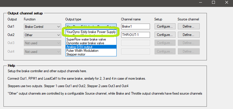
Default setting for dynoKRAFT dynamometers is YourDyno Eddy brake Power Supply.
Use the "Configure" button to setup the Bluetooth connection to PWS and manually control the retarder (function test).

Warning!
DO NOT change default voltage of 192V.
Risk of equipment damage and loss of warranty!
Use the "Define" button to adjust brake linearization although this is normally not needed on dynoKRAFT dynamometers.
Info
For more information on other Output types please refer to YourDyno manual (external link: https://yourdyno.com)
Throttle Control
In the Output channel setup an new function to control vehicles throttle has been introduced, with three different Output types:
- 0-5V analog
- PWM (incl. RC Pulse)
- Stepper Motor
For Ride-By-Wire systems the default setting is 0-5V.
PWM (RC pulse) or Stepper Motor is used with model and industrial servos or motors which in turn are used to pull the throttle Bowden-cable.
In Bowden-cable systems the output linearization can be used to remove slack from the system.
Ride-By-Wire
Info
Overriding the ride-by-wire signal requires in-depth knowledge of test vehicles electronic system and should be only performed by experienced technicians.
Additionally in most cases such operation will result in fault code being displayed in the vehicles cockpit.
In case of Ride-By-Wire system it is necessary to use additional signal amplifiers with galvanic insulation to prevent damage to ADAQ controller.
Additionally in some vehicles the 0-5V signal must be converted to 0-12V range, in almost every application duplicated and sometimes even inverted (i.e. KTM ride-by-wire throttle)
To be able to duplicate or invert and voltage signal it's necessary to use programmable analog signal inverters that can convert 0-5V DC input to 0-12V (12-0V) output or other adequate range depending on your vehicles electric system.
To adjust the output range either set the signal inverter output or trim the ADAQ 0-5V output to desired range using the "Configure" button:
To set the desired throttle position select the "Source channel" accordingly.
Use "Sequencer throttle" to use the new Sequencer test mode.
Alternatively any available Aux-Input can be used to control the Throttle Out by external 0-5V potentiometer.
Sequencer
This new Test Mode was designed to "play-back" actual datalogger files and allow the vehicle to automatically drive on an dynamometer.
It can also be used to define automatic brake-in procedure for rebuilt engines etc.
It uses standard .csv files with following structure:
Time ; Target RPM ; Throttle ; Record data (true/false) ; add. channel X ; add. channel Y, add. channel ....
Although the file extension is .seq the Sequencer can import .csv files directly from datalogger without any additional processing provided the first three columns (Time, RPM, Throttle) are provided in this order.
Info
Importing very large .csv files to sequencer (and setting them up as default file) will impact the time that is needed to open New Run / Gauges window significantly.
To avoid long delay in opening the Gauges window please use small/short sequencer file as default.
The additional channels are defined in "Sequencer configuration" plugin and can be used to operate external relay boards (such as gear changes or clutch using relay-driven pneumatic actuators, ignition switch, fans, fuel pumps etc...) and define Gear Ratio after each gear change if needed:
RPM Curve
This test mode is now updated to include not only "RPM vs. Time" but also "Brake % vs RPM" brake control strategy.
The settings for this test mode haven't been changed.
Related Articles
ADAQbase user manual
Introduction This user manual is an integral part of the dynoKRAFT ADAQbase dynamometer controller hardware. All described functions and settings are applicable for the original YourDyno controller. ©2022 dynoKRAFT GmbH, all rights reserved. This ...ADAQexiom user manual
Introduction This user manual is an integral part of the dynoKRAFT ADAQexiom expansion module hardware and software plugin. ©2022 dynoKRAFT GmbH, all rights reserved. This manual is copyrighted by dynoKRAFT GmbH, hereafter referred to as dynoKRAFT, ...MPS380 user manual
Introduction This user manual is an essential part of the dynoKRAFT MPS380 dynamometer. All functions and settings described apply to the original YourDyno software accordingly. This product and all it's components are an custom built device designed ...Xencelabs Quick Keys remote user manual
Introduction This user manual is an integral part of the dynoKRAFT ADAQ Software. The Xencelabs Quick Keys remote is a product of Xencelabs Technologies Ltd. (www.xencelabs.com) ©2022 dynoKRAFT GmbH, all rights reserved. This manual is copyrighted by ...A200- / A330- and A380-Series user manual
Introduction This user manual is an essential part of the dynoKRAFT A200-2WD / A200-4WD-ML / A330-2WD / A330-4WD-ML / A380-2WD and A380-4WD-ML dynamometer. All functions and settings described apply to the original YourDyno software accordingly. This ...